Hybrid System
May 01, 2026
Hybrid test platform pairing a small inline 4 engine with a brushless motor/generator, sensor network, embedded controller, and safety-focused state machine control.
System Overview
The hybrid system combines a small inline 4 engine, a BLDC motor/generator, battery management, cooling, load control, and data logging into one testbed. The main sensor set includes engine, BLDC, and cooling-system thermistors, current and voltage sensors for both load and generator sides, a load cell for fuel-consumption measurement, and tachometers for the generator and load.
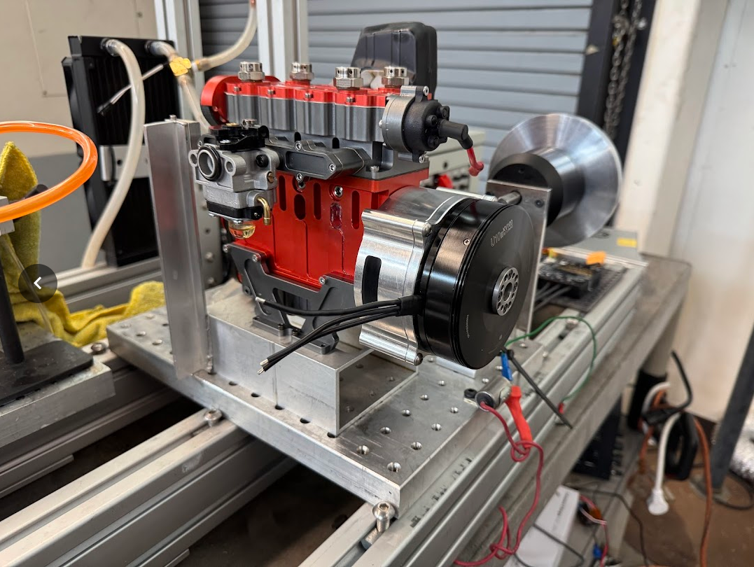
Physical Test Platform
The physical setup is built around an engine mounted to a rigid test frame with the brushless motor/generator coupled to the output side. The goal is to evaluate how the engine and electric machine can share power production while keeping the mechanical packaging serviceable and measurable.
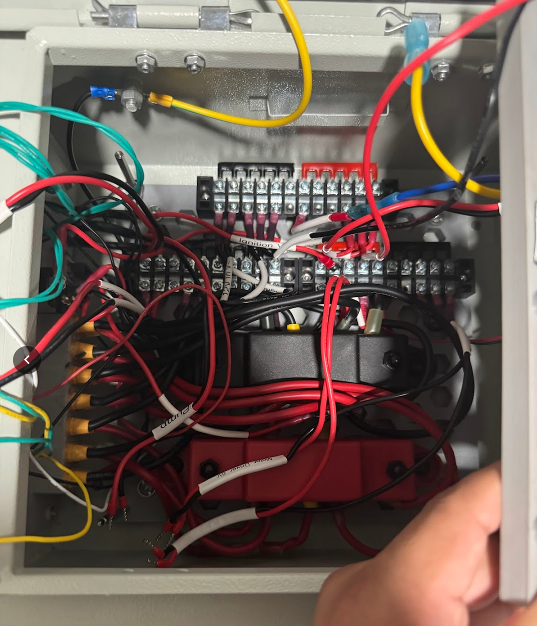
Electronics Box Wiring
The electronics box brings together terminal blocks, shielded cabling, power distribution, sensor connections, and controller interfaces so the test rig can be wired cleanly and serviced during experiments.
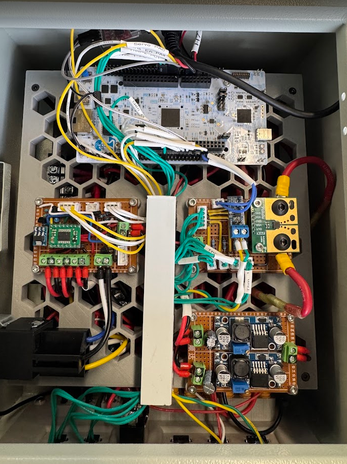
Electronics and Noise Control
The enclosure is designed to reduce electrical noise in the sensor signals. It uses shielded and grounded CAT6 wiring, filter capacitors where needed, and RC filtering on thermistor lines to improve sensor stability.
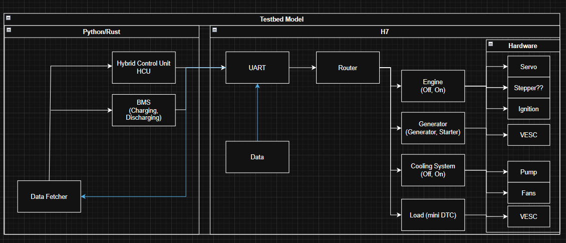
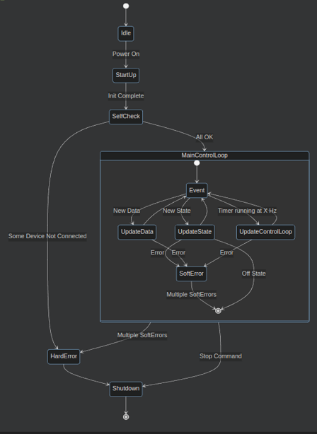
Control Structure
The control structure separates data fetching, state updates, and timer-driven control updates. The main loop handles new data, control-loop timing, soft errors, hard errors, stop commands, and shutdown behavior.
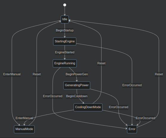
State Machines and Error Handling
The control architecture is organized around subsystem state machines. The state flow covers idle, startup, engine running, power generation, cooldown, manual mode, error handling, and reset behavior.
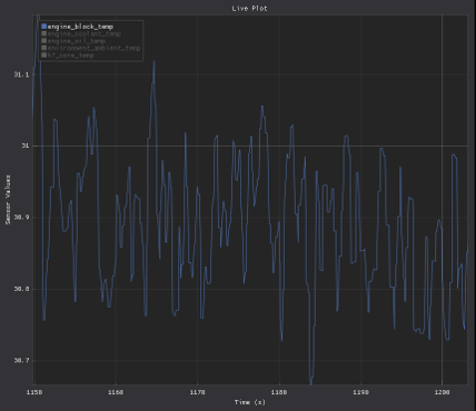
Sensor Filtering
The signal-processing work includes live filtering of noisy temperature data so the controller can work with cleaner thermistor readings instead of raw sensor noise.
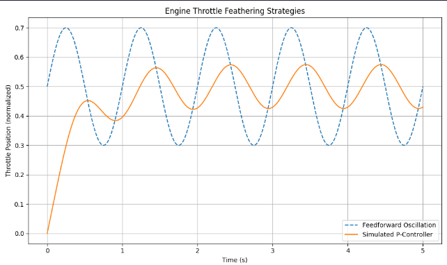
Servo Throttle Simulation
The servo simulation compares a feedforward oscillation against a simulated proportional controller response to evaluate smoother throttle feathering behavior.